Sharing of UART Communication Diagram Between Microcontrollers
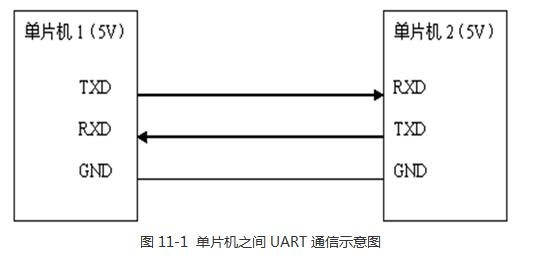
A microcontroller is an integrated circuit chip. It uses ultra-large-scale technology to integrate a microprocessor (CPU) with data processing capabilities, memory (including program memory ROM and data memory RAM), and input and output interface circuits (I/O interfaces) on the same chip to form a single chip. In other words, the small and complete computer hardware system can accurately, quickly, and efficiently complete the tasks specified by the program designer under the control of the single-chip microcomputer program. Therefore, a single-chip chip has all the functions of a computer. 1, SPI SPI allows high-speed synchronous data transfer between the microcontroller and the peripheral devices or the microcontroller. The SPI can have master and slave modes. The master and slave of the communication exchange data at the same time through the shift register. At present, most of them use host mode. SPI needs four lines: SS, MISO, MOSI, SCK. Communication process: In setting the working mode of SPI: Including SCK frequency (data transmission rate), working speed, master-slave mode, and data receiving and sending the corresponding clock polarity. In master mode, pull SS low to indicate the start of communication, and then start a communication by automatically starting the clock SCK after writing a byte of data into the SPI data register. After the communication is completed, a corresponding interrupt flag will be generated, indicating a The transmission of byte data is completed. After the communication is completed, the SS pin is pulled high, indicating that the communication process has ended. Note the setting of SS pin: when set to slave mode, SS pin should be set as input, SPI can work when pulled low, passive SPI mode when pulled high; SS pin can be in host mode The setting should generally be set to output. If it is set to input, it should be kept high. Otherwise, normal host mode operation cannot be performed. 2, USART The operation of the USART is relatively simple, mainly setting the baud rate, data format, and interrupt enable bit. It is worth mentioning that its USART IN SPI MODE, the operation of the USART in the SPI mode is similar to the SPI operation, mainly the setting of the Clock. , and then send the data or through the USART interrupt 3, I2C The I2C interface is a simple and powerful communication interface. It only requires two bidirectional buses (clock and data lines), SCL and SDA, and it can realize one host and up to 128 slaves for communication. The process of analog I2C interface: start I2C, generally when SCL is high, SDA is pulled low to start data transmission. SDA can only be pulled high when SCL is low. It is only used when SCL is high. Stops starting I2C communication I believe that many people are confused about how RXD and TXD are connected when the microcontroller is communicating with a computer or a chip. Because in some circuit diagrams, there are direct connection methods, and some are cross-connections that make people feel a bit confused. The first thing to understand is the two concepts, DTE and DCE. DTE refers to data terminal equipment. The typical DTE is a computer and a microcontroller. DCE refers to data communication equipment. The typical DCE is MODEM. The RXD and TXD in the RS232 serial port standard are all standing on the DTE stand, not the DCE. Understand this point, then talk about the following wiring method, it is easy to understand. When the SCM communicates with the computer through the serial port, the RXD of the SCM is connected to the TXD of the computer, and the TXD of the SCM is connected to the RXD of the computer. (1) Use a serial port. When designing the circuit, the RXD of the one-chip computer connects the TXD of the circuit board DB9, the TXD of the one-chip computer connects the RXD of the circuit board DB9 of the one-chip computer, the concrete realization can be reversed at the 232 level conversion chip. (2) Use a serial port crossover cable. When designing the circuit, because the serial line has already been crossed, the RXD of the one-chip computer connects the RXD of the circuit board DB9, the TXD of the one-chip computer's TXD connects the circuit board DB9, all can connect directly. This can explain why some circuits use the direct connection method, and some circuits use the crossover method, because the serial cable used is different. Communication can be divided into parallel communication and serial communication according to basic types. In parallel communication, each bit of data is transmitted at the same time, which can achieve byte-based communication, but the communication line occupies more resources and costs more. For example, we used P0 = 0xFE; we assign values ​​to the eight IO ports of P0 at a time and output signals at the same time. This is analogous to 8 lanes that can pass 8 cars at the same time. This form is parallel and we are used to it. Also referred to as P0, P1, P2, and P3 are four groups of 51 parallel busses. Serial communication is like a lane. Only one vehicle can pass at a time. If a byte of 0xFE is to be transmitted in the past, if the lower bit is behind the upper bit, then the sending method is 0-1-1. -1-1-1-1-1-1, sent by a single person, must send 8 times to send a byte. The STC89C52 has two pins dedicated to UART serial communication. One is P3.0 and the other is P3.1. They also have other names called RXD and TXD. The communication interface composed of them is called serial. Interface, referred to as serial port. Use two single-chip microcomputers to carry on the UART serial port communication, the basic demonstration diagram is shown as in Fig. 11-1. In the figure, GND indicates the reference ground for the microcontroller system power supply, TXD is the serial transmit pin, and RXD is the serial receive pin. The communication between the two MCUs is based on the same power supply reference. Therefore, we need to connect the GNDs of the two MCUs to each other. Then the TXD pin of MCU 1 is connected to the RXD pin of MCU 2. This is MCU 1. When the microcontroller 2 receives the channel, the RXD pin of MCU 1 is connected to the TXD pin of MCU 2. This is the channel that MCU 2 sends and MCU 1 receives. This diagram shows the process of sending and receiving information between two microcontrollers. When Microcontroller 1 wants to send data to Microcontroller 2, for example, it sends a 0xE4 data, which is expressed in binary format as 0b11100100. In the UART communication process, it is the principle of low-level, high-priority, and then let TXD first pull down the power. Ping, continue for a period of time, send a 0, then continue to pull down, continue for a period of time, send a 0 again, then pull high, continue for a period of time, sent a 1 „„until to 8 Binary digits 0b11100100 are all sent. The question here is the question of how long it lasts for this “period of timeâ€. This introduces an important concept in communication - baud rate, also called bit rate. The baud rate is the rate at which binary data bits are transmitted. It is customary to use baud, which means that we send a binary data for a duration of 1/baud. Before communication, SCM 1 and SCM 2 must first explicitly specify the communication baud rate between them, and they must be consistent. The sending and receiving parties can communicate normally. This must be clearly noted. After agreeing on speed, we must also consider the second question. When is the data the beginning and when is the end? Whether it is early reception or delayed reception, the data will receive an error. In the UART communication, a byte is 8 bits, which specifies that when there is no communication signal, the communication line is kept high. Before sending data, a 0 bit is used to indicate the start bit, and then 8 data bits are transmitted. The data bits are in the order of first low and high. After the data bits are sent out, a 1 is sent to indicate the stop bit. This would have sent a one-byte 8-bit data, but in fact we have sent a total of 10, and the extra two bits, one start bit and one stop bit. On the other hand, the receiver always maintains a high level. Once it detects a low level, it knows that it is time to start preparing to receive data. After receiving 8 bits of data, it then detects the stop bit and prepares for the next stop. A data reception. Let's take a look at the diagram, as shown in Figure 11-2. Figure 11-2 shows the schematic diagram of data transmission on the serial port. It is actually a schematic diagram of the time domain, that is, the correspondence of the signal with time. For example, on the sending pin of the SCM, the left side occurs first and the right side occurs later. The switching time of the data bit is one second of the baud rate. If you can understand the concept of the time domain, many communication timings are behind. The map is easy to understand. Multiple Beam Angles street lights,LED Street light,Led White Light Street lamp Kindwin Technology (H.K.) Limited , https://www.szktlled.com


