Deep interpretation of four-switch Buck-Boost circuit and converter
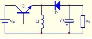
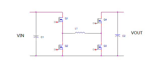
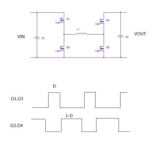
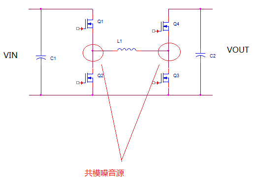
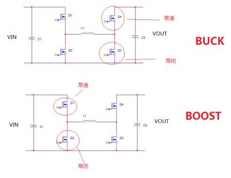
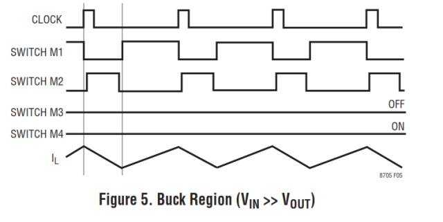
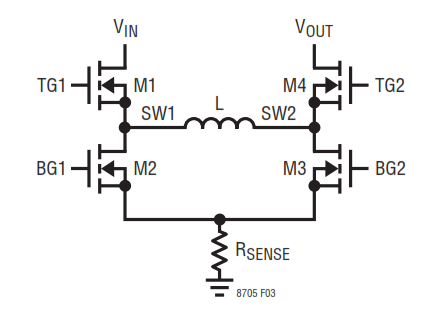
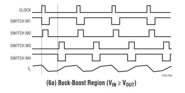
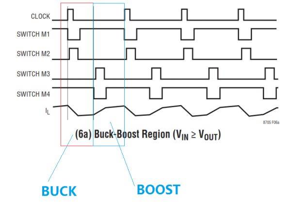
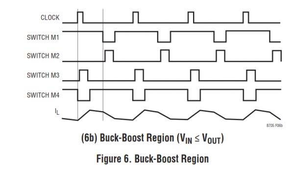
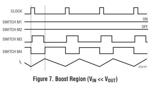
Discussion on four-switch Buck-Boost converter In non-isolated power solutions, Buck, Boost, and Buck-Boost circuits are very widely used, and many engineers are familiar with these three circuits. Let's talk about the four-switch Buck-Boost circuit. In a conventional Buck-Boost circuit, Vo=-Vin*D/(1-D), the polarity of the output voltage is opposite to the input voltage. A brief four-switch Buck-Boost circuit, Vo=Vin*D/(1-D), has the same polarity as the input voltage. The topology of the four-switch buck-boost is very simple, as shown below. For the four-switch buck-boost, it has a very traditional and simple control method. That is, Q1 and Q3 work at the same time, and Q2 and Q4 work at the same time. And the two groups of MOS are alternately turned on, as shown above. If you replace Q2 and Q4 with a diode, then it works the same, but there is no synchronous rectification. For this type of control, we can get the formula in the case of CCM: Vin*D=Vout(1-D) That is, Vout=Vin*D/(1-D). This voltage conversion ratio is the same as our usual buck-boost. Only the common buck-boost output voltage is negative, while the four-switch output is positive. But the advantage of this control method is simple, there is no modal switching. However, the disadvantage is that all four tubes are always working, the loss is large, and the common mode noise is also large. Based on the shortcomings of traditional control methods. Years ago, a well-known IC company introduced a control IC that revolutionized the control of this topology. The idea is to use this topology as a pure BUCK when Vin>Vout, when Vin However, this idea itself has nothing strange. What is really technical, what is the control method when VIn=Vout? How do you switch seamlessly from buck to intermediate mode and then to boost? These problems, later became various IC companies, opened their minds and competed for the battlefield of intellectual property. Next, let me introduce the control logic of a particular company's IC. First assume that the output is a fixed 12V, the input is assumed to be a battery, the full-charge voltage is 16V, and the discharge end voltage is 8V. Then from the input of 16V, the working state at this time is obviously BUCK Then the driving signals of the four tubes are as follows Then when the input battery voltage gradually starts to decrease, the duty ratio of M1 gradually starts to increase, and the duty ratio of M2 begins to decrease. At this time, the duty cycle of M2 is a key parameter. Because the IC has a minimum setting for the pulse width of M2, say 200ns. Now assume that the input voltage drops to 12.5V, and the pulse width of M2 shrinks to 200ns. The logic inside the IC is considered to be the time for modal switching. The change that occurred at this time was that the two tubes M3 and M4 were no longer normally closed and normally open, but started to switch. If we decompose the above image, we will find an interesting phenomenon, that is, in a clock cycle, the first half cycle is buck, and the second half cycle is boost. At this time, when boost is cut in, M3 is cut at the minimum duty ratio, and the duty ratio is not adjustable. At this time, the duty ratio of M2 will suddenly broaden from the minimum to offset the influence of the bow model. At this time, the output will produce a dynamic effect. Then, as the input continues to drop, the duty cycle of M2 will continue to decrease. Then when M2 returns to the minimum duty cycle again, the IC internal logic circuit will think that the modal needs to be converted again. At this point, M2 will be fixed at the minimum duty cycle, while M3 will begin to jump out of the minimum duty cycle and can be gradually widened. In theory, this transition should be a completely seamless switch. However, due to the switching of the clock timing inside the chip, it also has a dynamic effect on the output. At this time, it becomes boost in the first half and buck in the second half. Similarly, when the input voltage continues to decrease, the circuit will cut into the full boost mode. Of course, another IC giant, a certain instrument company has a similar IC, their biggest difference is the buck-boost mode. The IC of a certain instrument, in the buck-boost mode, is a cycle of buck, and the next cycle is boost, so recurrent. The IC of a certain company is in a cycle, the first half is buck, and the second half is boost. In general, the two are the same. We specialize in cable assembly overmolding. Our customized molded cables are built precisly following customers' spec.Experienced proposal can be offered to customers for evaluation by considering stable quality and competitive price.
Custom cable overmoldings improve the quality, look and functionality of many electrical cables. From battery interconnects and molded plugs to custom molded plugs and many other custom designed assemblies – ETOP is a premier custom cable overmolding supplier to OEMs.
Molded Cables,Stranded Round Molded Cables,Molded Patch Cord Cable,4 Pole Waterproof Molded Cable,Waterproof Connectors ETOP WIREHARNESS LIMITED , https://www.etopwireharness.com