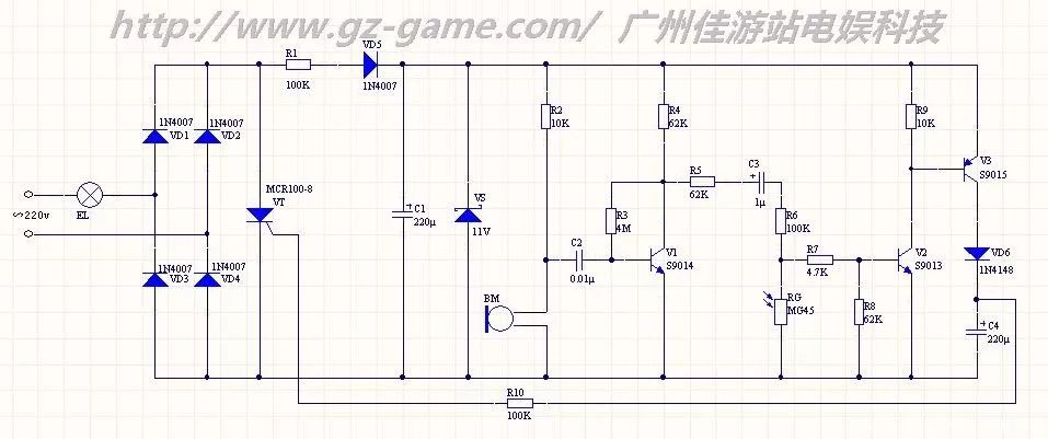
Detailed schematic diagram of the circuit diagram of the commonly used sound and light street lamp controller
This circuit is the schematic diagram of the sound and light street lamp controller commonly used in the market. The 220V mains has a bridge rectifier output ripple voltage composed of VD1~VD4. After R1, VD5, C1 step-down filtering, the VS provides 11V stability. DC voltage, providing power supply to the control circuit. In the static standby state: BM has no signal input, V1 is in the static amplification state. Because of the DC blocking function, the V2 base has no bias voltage and is in the off state, resulting in V3 of V3 being 0, so that V3 is also in the off state, above C4. No voltage, the control pole of VT does not provide enough conduction voltage, VT is in the off state, EL does not have enough current, and is in the extinguished state. When the ambient light intensity is sufficient: RG exhibits a low-impedance state. Even if C3 is short-circuited, the base of V2 does not get enough bias voltage and is in the off state, resulting in Vbe of V3 being 0, so that V3 is also in the off state, above C4. No voltage, the control pole of VT does not provide enough conduction voltage, VT is in the off state, EL does not have enough current, and is in the extinguished state. When the external light intensity is weak and there is no sound signal: RG exhibits a high-impedance state, which can be regarded as an open state compared with the resistance values ​​of R7 and R8, but the V2 base has no bias voltage due to the DC-blocking effect of C3. In the off state, Vbe of V3 is 0, so V3 is also in the off state, there is no voltage on C4, the control pole of VT does not provide enough on-voltage, VT is in the off state, EL does not have enough current, and is in the off state. When the external light intensity is weak and there is a sound signal: RG exhibits a high impedance state, which can be regarded as an open state compared with the resistance values ​​of R7 and R8. The audio signal output by the BM is amplified by V1 to produce an extremely high amplitude audio signal at its collector. The positive polarity of the amplified audio signal is sufficient for V2 after being divided by R5, R6, R7 and R8. Strong base bias, V2 enters the conduction state, causing V3 to enter the saturated conduction state. The power supply is charged to C4 through V3 and VD6. Since the frequency of the audio signal is not high and the sound signal has a certain duration, C4 is here. During the period of time, it can be fully charged to about 10V. At this time, C4 provides sufficient conduction voltage for the thyristor VT through R10, and the EL obtains sufficient current and is in a light-emitting state. When the sound signal disappears, since VD6 is reverse biased, the charge on C4 can only be discharged through R10 and VT, while the discharge time constants of C4 and R10 are relatively large, and VT will remain continuously until the voltage on C4 is insufficient. When VT is turned on, the EL returns to the extinguished state. According to the above analysis, if the sound sensitivity of the controller is to be adjusted, it can be realized by adjusting the resistance value of R4. When the resistance value of R4 is increased, the sound sensitivity can be lowered, and vice versa, the sound sensitivity is improved. If you want to adjust the light sensitivity of the controller, you can adjust the resistance of R8. When the resistance of R8 increases, the illuminance of the controller can be improved. Otherwise, the illuminance of the controller can be reduced. R4 and R8 independently adjust the sensitivity of each other and have little influence on each other. If R5 and R6 are adjusted, the sensitivity of both parameters will be affected and changed. The maximum power limit of EL of this circuit lies in the maximum current of VD1~VD4 and the maximum current of VT. According to the device selection in this circuit, the maximum allowable current is 1A, so the power of EL should be limited to 220W or less, leaving a margin. The EL is preferably 100 W or less.
The JUK universal Screw Terminal Block series has the typical features which are decisive for practical applications:
l The universal foot allows the terminal blocks to be easily snapped onto the NS35 or NS32 DIN Rail with G shape.
l Closed screw guide holes ensure screwdriver operation perfect.
l For terminal block with different wire cross-sectional areas, complete accessories are available, such as end plates, partition plates, etc.
l Potential distribution achieved by fixed bridges in the terminal center or insertion bridges in the clamping space.
l Same shape and pitch Grounding Terminal Blocks as the JUK universal series.
l Adopt ZB marker strip system,achieve unified identification.
Terminal Blocks Connector ,Electric Terminal Blocks Connector,Plastic Terminal Block,F Type Terminal Block Connector Wonke Electric CO.,Ltd. , https://www.wkdq-electric.com